


CAST IRONS, like steels, are essentially alloys of iron and carbon, but whereas the carbon content of steel is limited to a maximum of 2%, cast irons generally contain more than 2% carbon.
To facilitate a better understanding of these materials, they can be divided into five groups, based on composition and metallurgical structure: white cast iron, malleable cast iron, grey cast iron, ductile cast iron and alloy cast iron.
White Cast Iron
White cast iron derives its name from the white, crystalline crack surface observed when a casting fractures. Most white cast irons contain <4,3% carbon, with low silicon contents to inhibit the precipitation of carbon as graphite.
It is used in applications where abrasion resistance is important and ductility not required, such as liners for cement mixers, ball mills, certain types of drawing dies and extrusion nozzles.
White cast iron is generally considered unweldable. The absence of any ductility that can accommodate welding-induced stresses in the base metal and heat affected zone adjacent to the weld results in cracking during cooling after welding.
Malleable Cast Iron
Malleablecastironisproducedbyheattreatingwhitecastironofasuitablecomposition.Iron carbide can decompose in to iron and carbon undercertain conditions. This reaction is favored by high temperatures, slow cooling ratesand high carbon and silicon contents.
Ferritic Malleable Cast Iron
At room temperature, the microstructure therefore consists of temper carbon nodules in a ferrite matrix, generally known as ferritic malleable cast iron. The compact nodules of temper
carbon do not break up the continuity of the tough ferritic matrix, resulting in high strength and improved ductility. The graphite nodules also serve to lubricate cutting tools, which accounts for the very high machinability of malleable cast iron.
Ferritic malleable cast iron has been widely used for automotive, agricultural and railroad equipment; expansion joints and railing castings on bridges; chain-hoist assemblies; industrial casters; pipe fittings; and many applications in general hardware.
Perlitic Malleable Cast Iron
If full graphitisation is prevented and a controlled amount of carbon remains in the iron during cooling, finely distributed iron carbide plates nucleate in the iron at lower temperatures. This can be achieved by alloying with manganese, or by replacing the second-stage anneal by a quench (usually in air or oil).
Grey Cast Iron
Grey cast iron is one of the most widely used casting alloys and typically contains between 2,5% and 4% carbon and between 1% and 3% silicon. With proper control of the carbon and silicon contents and the cooling rate, the formation of iron carbide during solidification is suppressed entirely, and graphite precipitates directly from the melt as irregular, generally elongated and curved flakes in an iron matrix saturated with carbon.
When a grey iron casting fractures, the crack path follows these graphite flakes and the fracture surface appears grey because of the presence of exposed graphite.
The strength of grey cast iron depends almost entirely on the matrix in which these graphite flakes are embedded. Slow cooling rates and high carbon and silicon contents promote full graphitisation, and the majority of the carbon dissolved in the iron at high temperatures is deposited as graphite on the existing flakes during cooling. The structure then consists of graphite flakes in a ferrite matrix, referred to as ferritic grey cast iron.
If graphitisation of the carbon dissolved in the iron at high temperatures is prevented during cooling, iron carbide precipitates out and the matrix is perlitic (referred to as perlitic grey cast iron). Ferritic grey cast iron is normally soft and weak.
Ductile Iron
Ductile cast iron, also known as nodular iron or spheroidal graphite (SG) iron, is very similar in composition to grey cast iron, but the free graphite in these alloys precipitates from the melt
as spherical particles rather than flakes. This is accomplished through the addition of small amounts of magnesium or cerium to the ladle just before casting. The spherical graphite particles do not disrupt the continuity of the matrix to the same extent as graphite flakes, resulting in higher strength and toughness compared with grey cast iron of similar composition.
Typical applications are agricultural (tractor and implement parts); automotive and diesel (crankshafts, pistons and cylinder heads); electrical fittings, switch boxes, motor frames and circuit breaker parts; mining (hoist drums, drive pulleys, fly wheels and elevator buckets); steel mill (work rolls, furnace doors, table rolls and bearings); and tool and die (wrenches, levers, clamp frames, chuck bodies and dies for shaping steel, aluminium, brass, bronze and titanium).
Mechanical Properties
Due to the low toughness and ductility of cast iron (especially white and grey cast iron), standard tensile and impact toughness tests have limited applicability, and elongation and absorbed energy values are not always available. Some of the mechanical properties of the different types of cast iron are shown in the table below. The wide variation in mechanical properties within a particular class of cast iron, as shown below, can be attributed to a variation in microstructure.
The machinability of grey, malleable and ductile cast irons is superior to that of carbon steel, and these alloys even outperform free-cutting steel. The excellent machinability can be attributed to the lubricating effect of the graphite particles in the microstructure. Grey cast iron has a very high damping capacity (ability to quell vibrations) and is therefore well suited for bases and supports, as well as for moving parts.
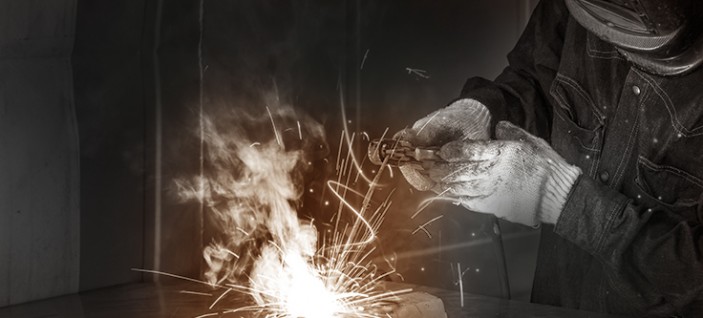
Welding
Cast irons include a large family of ferrous alloys covering a wide range of chemical compositions and metallurgical microstructures. Some of these materials are readily weldable, while others require great care to produce sound welds. Certain cast irons are considered unweldable.
A major factor contributing to the difficulty of welding cast iron is its lack of ductility. If cast irons are loaded beyond their yield points, they break rather than deform to any significant extent. Weld filler metal and part configuration should therefore be selected to minimise welding stresses.
MMA, flux cored arc, MIG, TIG and gas welding processes are normally used with nickel-based welding consumables to produce high-quality welds, but cast iron and steel electrodes can also produce satisfactory welds in certain alloys.
Iron castings are generally welded to:
- Repair defects in order to salvage or upgrade a casting before service.
- Repair damaged or worn castings, and Fabricate castings into welded assemblies.
- Repair of defects in new iron castings represents the largest single application of welding cast irons.
Defects such as porosity, sand inclusions, cold shuts, washouts and shifts are commonly repaired. Fabrication errors, such as inaccurate machining and misaligned holes, can also be weld repaired.
Due to the widely differing weldability of the various classes of cast iron, welding procedures must be suited to the type of cast iron to be welded.
White Cast Iron
Because of its extreme hardness and brittleness, white cast iron is considered unweldable.
Malleable Cast Iron
During welding, the ductility of the heat affected zone (HAZ) of malleable cast iron is severely reduced because graphite dissolves and precipitates as iron carbide. Although post weld annealing softens the hardened zone, minimal ductility is regained. Despite these limitations, malleable cast irons can be welded satisfactorily and economically if precautions are taken.
Because most malleable iron castings are small, preheating is seldom required. If desired, small welded parts can be stress relieved at temperatures up to 550°C. For heavy sections and highly restrained joints, preheating at temperatures up to 200°C and a post weld malleabilising heat treatment are recommended. However, this costly practice is not always followed, especially when the design of the component is based on reduced strength properties of the welded joint.
Ferritic malleable grades display the best weldability of the malleable cast irons, even though impact strength is reduced by welding. Perlitic malleable irons, because of their higher combined carbon content, have lower impact strength and higher crack susceptibility when welded. If a repaired area must be machined, welding should be performed with a nickel-based electrode.
MMA welding cast iron, using low carbon steel and low hydrogen electrodes at low currents, produces satisfactory welds in malleable iron. If low carbon steel electrodes are used, the part should be annealed to reduce the hardness in the weld (due to carbon pick-up) and in the HAZ.
Grey Cast Iron
As grey cast iron contains graphite in flake form, carbon can readily be introduced into the weld pool, causing weld metal embrittlement. Consequently, techniques that minimise base metal dilution are recommended. Care must be taken to compensate for shrinkage stresses, and the use of low strength filler metals helps reduce cracking without sacrificing overall joint strength.
Grey cast iron welds are susceptible to the formation of porosity. This can be controlled by lowering the amount of dilution with the base metal, or by slowing the cooling rate so that gas has time to escape. Preheat helps reduce porosity and reduces the cracking tendency. A minimum preheat of 200°C is recommended, but 315°C is generally used.
The most common arc welding electrodes for grey cast iron are nickel and nickel-iron types. These electrodes have been used with or without preheating and/or post weld heat treatment. Cast iron and steel electrodes must be used with high preheats (550°C) to prevent cracking and the formation of hard deposits.
Ductile Cast Iron
Ductile cast irons are generally more weldable than grey cast irons, but require specialised welding procedures and filler materials. Perlitic ductile iron produces a larger amount of martensite in the HAZ than ferritic ductile iron and is generally more susceptible to cracking.
MMA, using nickel-iron electrodes, is the most common welding technique for welding ductile iron. Most castings do not require preheating, but preheats of up to 315°C are used on large components.
Electrodes should be dried to minimise hydrogen damage and porosity. If machinability or optimum joint properties are desired, castings should be annealed immediately after welding.
| Cast Iron | Tensile Strength ( MPa) | Compressive Strength ( MPa) | Hardness (HB) | Elongation (%) | Toughness (J) |
| White | 200 – 410 | Not available | 321 – 500 | Very low | Very low |
| Malleable | 276 – 724 | 1350 – 3600 (perlitic and martensitic) | 110 – 156 (ferritic) 149 – 321 (perlitic and martensitic) | 1 – 10 | 4 – 12 J @ 20°C |
| Grey | 152 – 431 | 572 – 1293 | 156 – 302 | <0,6 | Very low |
| Ductile | 345 – 827 | 359 – 920 | 143 – 302 | 2 – 20 | 16 – 27 J @ 20°C |
Practical Considerations Base Metal Preparation
Proper preparation of a casting prior to welding is very important. All traces of the defect must be removed from the casting, usually by chipping, grinding, arc gouging or flame gouging. Dye-penetrant inspection is recommended to ensure complete removal of all defects. Thorough cleaning of the joint faces and adjacent material prior to welding is essential to ensure successful repair welding and to prevent porosity and wetting difficulties.
Castings that have been in service are often saturated with oil or grease. Exposure to high temperatures during the weld thermal cycle can cause dissociation of these hydrocarbon compounds, resulting in the formation of porosity in the weld. For this reason, any surface oil or grease must be removed prior to welding, using solvents or steam cleaning. The surface skin of the casting, which may contain burned-in sand or other impurities from the mould, should also be removed. Castings that have been in service for extended periods of time may also require degassing by heating the casting uniformly to about 370°C for 30 minutes, or for a shorter time to almost red heat (approximately 540°C), using an oxy-fuel gas torch or circulating air furnace.
If localized degassing is preferred, the weld area can be heated by depositing a weld pass, which usually becomes very porous, and then removing it by grinding. This welding and grinding operation is repeated until the weld metal is sound. The weld may then be completed as specified in the welding procedure. Castings that have been impregnated with a plastic or glass sealer should not be repair welded, because the sealer may inhibit fusion or produce excessive porosity in the weld.
It is also important that the outer surface of the casting and any ground surfaces be wiped with mineral spirits, such as acetone, to remove residual surface graphite prior to welding. Residual graphite inhibits wetting and prevents complete joining and fusion. When wetting difficulties are encountered, the following cleaning methods can be used:
Electro chemical cleaning in a molten salt bath operating at a temperature of 455–510°C in a steel tank. By passing direct current through the bath, a surface essentially free of graphite, sand, silicon, oxides and other contaminants can be produced.
Abrasive blasting with steel shot is suitable for preparing the surfaces of ductile and malleable cast iron, but should not be used for grey cast iron.
Searing the surfaces to be welded with an oxidizing flame or heating the casting to about 900°C in a strongly decarburising atmosphere, may be suitable in some applications.
Before any cleaning procedures are used in production, wetting tests should be conducted, using the proposed filler metal and welding procedure. The filler metal should be applied to a clean, flat surface and then examined visually. If the surface is not uniformly wetted, it has not been cleaned sufficiently.
Special Welding Techniques for Cast Irons
Improved weld performance can be achieved by application of several special techniques. These include:
- Joint design modifications Groove face grooving Studding.
- Peening.
- Special deposition sequences and electrode manipulation.
- Joint Design Modification.
Full penetration welds are better than partial penetration ones, since the crevice left unfused can act as a stress concentration, increasing the risk of cracking. It is therefore advisable, where possible, to modify joint design to allow full penetration weld to be made, as shown below. Welds at changes in thickness can suffer uneven expansion and contraction stresses during the welding cycle, and also are located at stress concentrations.
A change in design to move the weld to a region of constant thickness is therefore beneficial in some cases, since the weld is then removed from the ‘danger area’. A backing fillet weld can also be used to support a weld in a region of stress concentration.
Groove Face Grooving
Grinding or gouging grooves into the surface of the prepared weld groove, then filling the grooves with a weld bead, before filling the whole joint, as shown opposite, is sometimes recommended. This reduces the risk of cracking by deflecting the path of a crack. Also, as with conventional buttering, the beads that are in contact with the casting, and therefore most highly diluted, are deposited first, when the stresses on the fusion line and heat affected zone of the weld are lowest.
The technique of grooving the joint face before filling. This interrupts the line of the heat affected zone.
Studding
Improved joint strength can be achieved by driving or threading studs into the joint face. These should be staggered as shown below, so that a stud does not face another directly opposite it across the joint. Provided the studs are of material compatible with the filler metal, this technique can help reduce underbead cracking in the HAZ or along the fusion line.
Peening
By hammering (peening) a deformable weld bead, and thereby putting it into a state of compressive stress, the tensile stresses caused by thermal contraction can be opposed, thus reducing the risk of cracking in and around the weld. This requires a ductile weld metal. Nickel fillers are very suitable and, when welding brittle grey cast irons, this process is extremely useful. When stronger joints are required and iron-nickel consumables are used, then peening must be done at higher temperatures, while the metal is still sufficiently soft. Peening can be mechanized or done manually. For manual work, a 13–19 mm ballpeen hammer is used to strike moderate blows perpendicular to the weld surface. Mechanized hammers should operate at 620 kPa and at 750–1 000 mm/min. The hammer head should be no wider than the weld bead and should have a radius equal to half the width.
Deposition Techniques and Electrode Manipulation
Arc Welding
Stringer or weave techniques can be used in depositing the weld bead, though weaving should be kept to within three times the electrode core diameter. Minimum dilution will result from using the stringer technique in the flat position, with the arc directed at the weld pool rather than the base metal. When re-striking the arc, this should be done on deposited metal, rather than base metal, though any slag must first be removed. This can be done with a cold chisel or chipping hammer.
In long welds, or welds on thick base material, depositing short, staggered beads will help minimize distortion, by balancing contraction stresses. Buttering of thick joint faces before filling in the rest of the joint is recommended. This is particularly effective if the buttering layers are of a composition more tolerant to dilution by the base metal.
To minimize penetration, short circuit dip-transfer modes should be used with MIG, MAG and flux cored welding processes, and arc lengths in MMA welding should be kept as short as possible while still maintaining good weld shape. In general, the welding current should be kept as low as possible within the range specified by the consumable manufacturer.
Oxy-Acetylene Welding
When depositing cast iron by the gas welding process, the torch flame should not be oxidising, as the resulting loss of silicon promotes the formation of brittle white iron in the deposit. Similarly, the tip of the inner cone of the flame should be kept between 3 and 6 mm from the casting surface, and should not actually touch. The welding rod should be melted by immersion into the molten weld pool, and not melted directly by the torch flame.
Two types of sequence are recommended for depositing cast iron by gas welding. With the so-called ‘block’ sequence, filler metal can either be deposited in blocks of ~2,5 cm, before filling between the blocks. With the so-called ‘cascade’ sequence, thin layers are deposited, with each one being slightly longer than the preceding one. Both the block and cascade sequences are illustrated above.
Braze Welding
Since this process is particularly sensitive to the wetting of the base metal surface by the filler, cleanliness of the iron before welding is essential. This means that smeared graphite on the surface after grinding must be removed. The bronze welding rod is melted by contact with the base metal after preheating by the gas flame to 425–480°C. The slightly oxidizing inner core of the flame should not be brought into contact with the consumable rod or the base metal. The rounded edges recommended for the joint faces in bronze welding increase the interface area between the casting and the deposited metal.
Cracking
All cast irons have a common problem affecting their weldability, namely their high carbon contents. Welding of cast iron is associated with rapid cooling of the weld pool and adjacent base metal, compared with the slower cooling rates experienced during casting, and tends to produce undesirable micro-structures, such as iron carbide and high-carbon martensite.
Martensite and iron carbide are both very brittle and may cause cracking, either spontaneous or during service. The degree of embrittlement depends on the amount of iron carbide and martensite formed, which in turn depends on the cast iron composition and thermal treatment. The presence of hard, brittle martensite in the HAZ also increases the risk of hydrogen-induced cracking.
Martensite in the HAZ may be tempered to a lower strength or a more ductile structure during post weld heat treatment, or it may be totally eliminated by ensuring very slow cooling rates after welding. Multiple-pass welding and minimum preheat and inter-pass temperatures are commonly specified to retard the cooling of cast iron welds and to prevent the transformation to martensite. Alternatively, welding procedures designed to reduce the size of the HAZ, and thus minimize cracking, can be used. Methods of accomplishing this include:
- Reduction of heat input.
- Use of small-diameter electrodes.
- Use of low melting point welding rods and wires.
- Use of lower preheat temperatures.